


Three-phase short-circuiting device for MV OHL line – application from the ground or height – CAA clamp
![]()
![]()
.
Intended use: earthing and short-circuiting of conductors of MV overhead line conductors..
Application: from the ground or from height (from the ladder, from the basket), by hanging the self-locking clamps (CAA) on the conductor, followed by the pulling down the clamp, which is automatically removed from the clamp applicator.
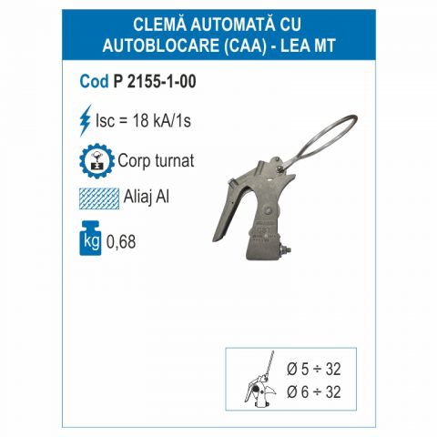
Automatic self-locking clamps (CAA) must be handled with insulating sticks appropriate to the installation and mounting position.
The following sequence of operations shall be observed:
1. By means of the earthing subassembly, one conductor of the line is earthed
2. By means of the short-circuiting subassembly, the three conductors of the line are short-circuited, starting with the conductor earthed in the previous operation.
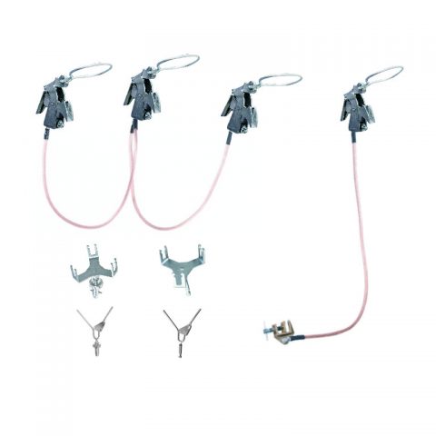
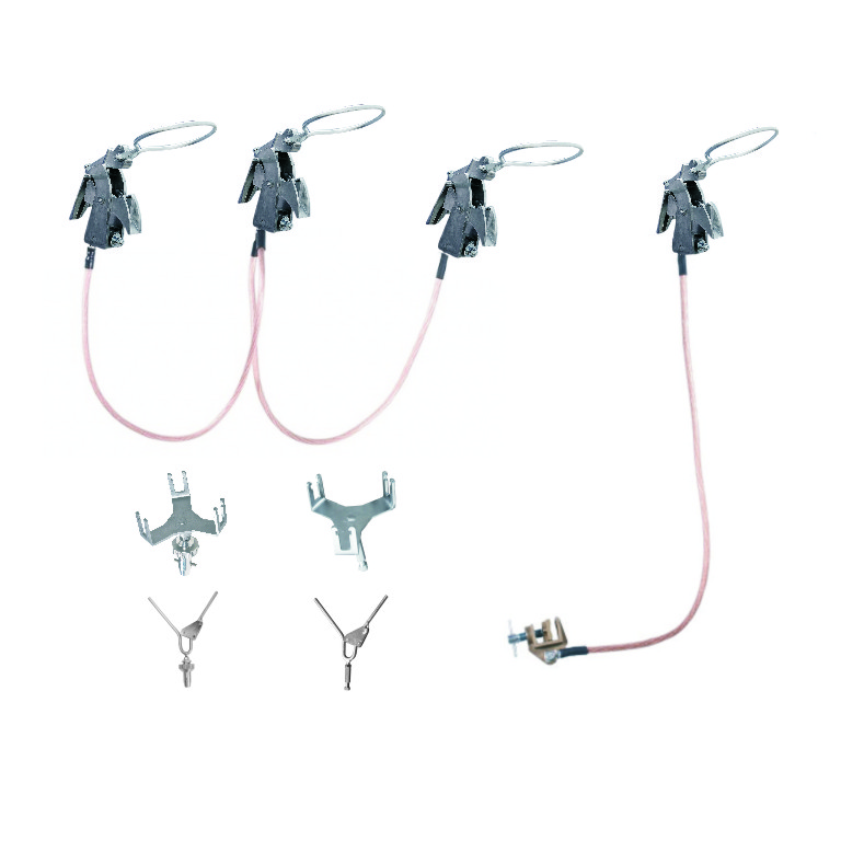
Components:
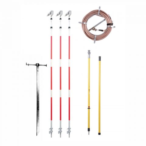
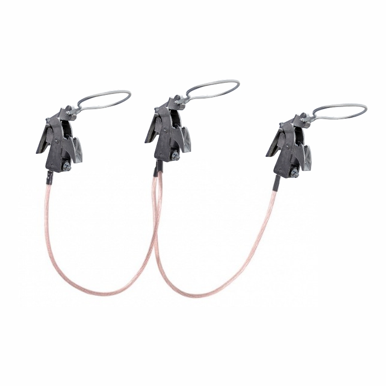
The short-circuiting subassembly for 3 overhead conductors includes the following components:
- Automatic self-locking clamp (CAA) – 3 pieces
- Short-circuiting cable – 2 pieces
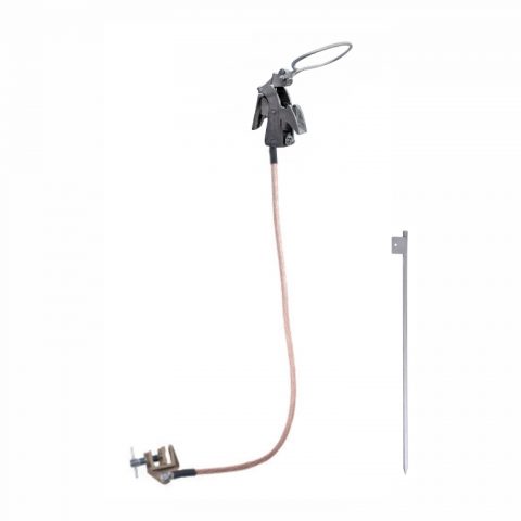
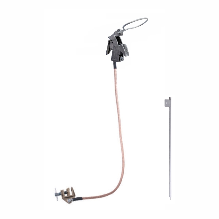
The earthing subassembly includes the following components:
- Automatic self-locking clamp (CAA) – 1 piece
- Earthing cable – 1 piece
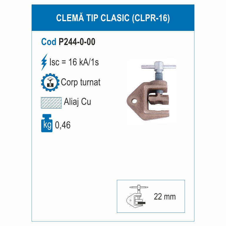
- Manual earthing clamp – 1 piece
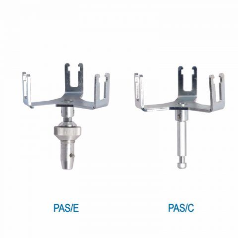
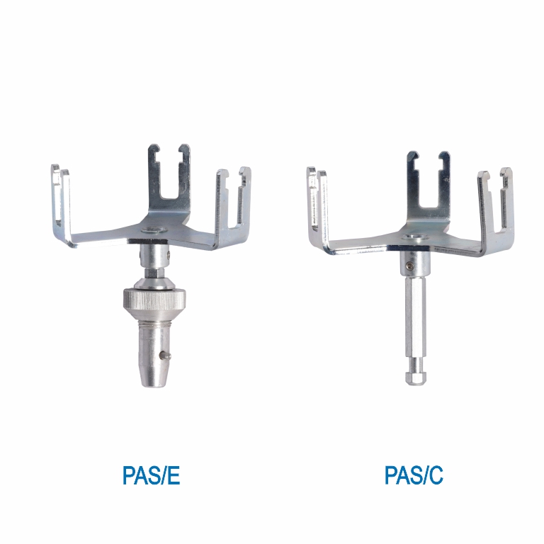
- Clamp applicator (PAS/E sau PAS/C) – 1 piece
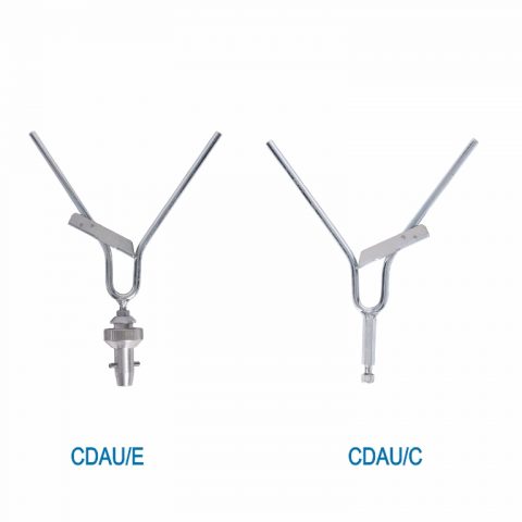
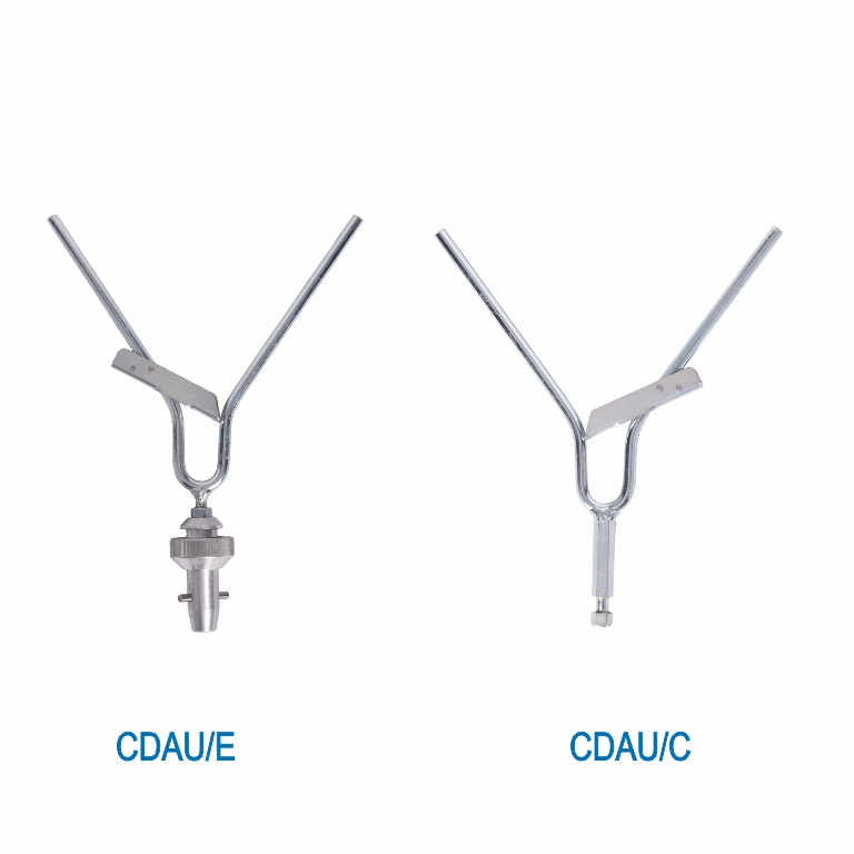
- Removal fork (CDAU/E sau CDAU/C) – 1 piece
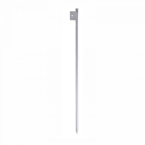
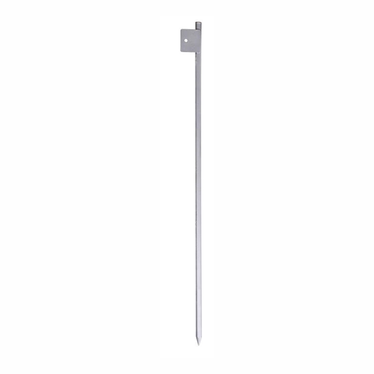
- Mobile earthing electrode (peg) – 1 piece
Packing: waterproof bag.
Other equipments to be used:
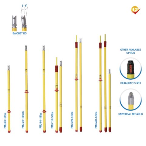
– connectable insulating stick type PMU 20-1 B/ba or PMU 20-1 B/baS (for application from height), provided with ‘’RO bayonet’’ coupling system
– telescopic insulating stick type PTU 20-35 F, PTU 20-110 F or PTU 20-45-110F 9for application from height), provided with ‘’hexagon 12’’ coupling system
– telescopic insulating stick type PTU-AS-400-6-c (for application from the ground), provided with ‘’hexagon 12’’ coupling system
Tips: coupling ends of the clamp applicator and of the removal fork must be selected to be adapted to the coupling system of the insulating stick used.
|
Technical characteristics |
Value |
||
|
Earthing Sp cable cross-section (mm2) |
16 |
25 |
35 |
|
Nominal short-circuit for t = 1 s Isc (kA) |
4 |
6,25 |
8 |
|
Shock (peak) nominal current for t = 0,02 s Isd (kA) |
10 |
15,63 |
20 |
|
Test short-circuit current for t = 1 s (kA) |
4,6 |
7,2 |
9,2 |
|
Test (shock) peak current for t = 0,02 s (kA) |
11,5 |
17,97 |
23 |
|
Power factor (according SR EN 61230) |
2,5 |
||
|
Length of phase cable lf (m) |
max. 4 |
||
|
Length of earthing cable lp (m) |
max. 15 |
||
|
Diameter of the conductor where the phase clamp can be applied (mm) |
5 – 32 |
||
Components:
The short-circuiting subassembly for 3 overhead conductors includes the following components:
- Automatic self-locking clamp (CAA) – 3 pieces
- Short-circuiting cable – 2 pieces
The earthing subassembly includes the following components:
- Automatic self-locking clamp (CAA) – 1 piece
- Earthing cable – 1 piece
- Manual earthing clamp – 1 piece
- Clamp applicator (PAS/E sau PAS/C) – 1 piece
- Removal fork (CDAU/E sau CDAU/C) – 1 piece
- Mobile earthing electrode (peg) – 1 piece
