

ESE piezoelectric lightning conductor – Saint-Elme type
ESE piezoelectric lightning conductor - Saint-Elme type
![]()
![]()
![]()
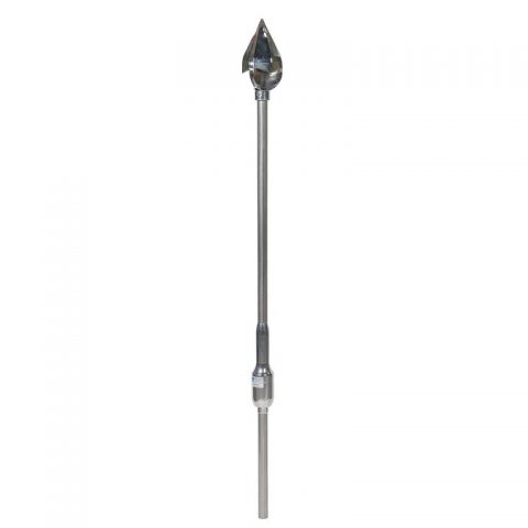
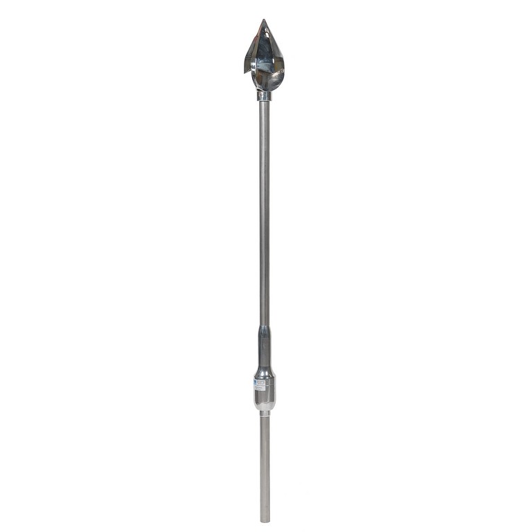
ESE piezoelectric lightning conductor type Saint-Elme
A rod-type lightning conductor, connected to earth, efficiently works by altering, at its level, the equipotentials which match the structures of the building it protects. The emergence of the lightning conductor is an important factor in increasing the local electric field. The principle of the piezoelectric lightning conductor designed by Franklin France relies on several factors: the reinforcement of the local electric field and the early creation of a preferential discharge channel.
The Saint Elme® piezoelectric lightning conductor is mainly composed of the following:
1. Capture head
Profiled, inalterable and good conductor, structured to generate a forced air circulation at its tip and in its prolongation (VENTURI system: air intakes and peripheral ejectors).
2. Support pole
Of treated copper (or stainless steel according to models) which upper part has one or more stainless steel ion emitter points, inserted in an insulating sleeve and subjected to the potential supplied by the piezoelectric ceramic.
The emitter points are protected from direct impact by lightning and from the weather by the capture head which, like the support pole, is permanently connected to the earth potential.
3. Transducer (piezoelectric stimulator)
Built into the lower part of the pole and consisting of piezoelectric ceramics stressed in an insulating container, combined with a simple, perfectly reliable and mechanical stimulation system (CEA and FRANKLIN patents). A high-voltage cable running inside the pole connects the stimulator to the emitter point(s). The voltage created by the ceramic is applied to the emitter point through the high voltage cable.
Saint Elme® piezoelectric lightning conductor has a 2 year warranty.
Click here to watch how a lighting conductor is mounted
|
Type |
SE6 |
SE9 |
SE12 |
SE15 |
||||||||||||
|
Excitation advance |
ΔT = 15 µs |
ΔT = 30 µs |
ΔT = 45 µs |
ΔT = 60 µs |
||||||||||||
|
Protection level |
I |
II |
III |
IV |
I |
II |
III |
IV |
I |
II |
III |
IV |
I |
II |
III |
IV |
|
Hinstall (m) |
Rp (m) |
Rp (m) |
Rp (m) |
Rp (m) |
||||||||||||
|
2 |
13 |
15 |
18 |
20 |
19 |
21 |
25 |
28 |
25 |
28 |
32 |
36 |
31 |
34 |
39 |
43 |
|
3 |
19 |
22 |
27 |
31 |
28 |
33 |
38 |
43 |
38 |
43 |
49 |
53 |
47 |
52 |
58 |
64 |
|
4 |
25 |
29 |
36 |
41 |
38 |
43 |
51 |
57 |
51 |
57 |
65 |
72 |
63 |
69 |
78 |
85 |
|
5 |
32 |
37 |
45 |
51 |
48 |
55 |
63 |
71 |
63 |
71 |
81 |
89 |
79 |
86 |
97 |
107 |
|
6 |
32 |
38 |
46 |
52 |
48 |
55 |
64 |
72 |
63 |
71 |
81 |
90 |
79 |
87 |
97 |
107 |
|
8 |
33 |
39 |
47 |
54 |
49 |
56 |
65 |
73 |
64 |
72 |
82 |
91 |
79 |
87 |
98 |
108 |
|
10 |
34 |
40 |
49 |
56 |
49 |
57 |
66 |
75 |
64 |
72 |
83 |
92 |
79 |
88 |
99 |
109 |
|
20 |
35 |
44 |
55 |
63 |
50 |
59 |
71 |
81 |
65 |
74 |
86 |
97 |
80 |
89 |
102 |
113 |
|
30 |
35 |
45 |
58 |
69 |
50 |
60 |
73 |
85 |
65 |
75 |
89 |
101 |
80 |
90 |
104 |
116 |
|
60 |
35 |
45 |
58 |
75 |
50 |
60 |
75 |
90 |
65 |
75 |
90 |
105 |
80 |
90 |
105 |
120 |
Hinstall = mounting height, compared to the highest point (elevation) of the building
Rp = radius of protection, depending on the mounting height and the level of protection