- Electrical Safety Devices
- Personal Protective Equipment
- Collective Protective Equipment
- Insulating Equipment
- Live Working Equipment
- Insulating Sticks and Accessories
- Voltage Detectors
- Testers
- Earthing devices for low voltage
- Earthing devices for MV / HV overhead lines
- Earthing devices for substations
- Miscellaneous earthing devices
- Phase clamps / earthing clamps
- Accessories for mobile earthing devices
- Miscellaneous equipment
- Periodical Inspections
- Equipment for Work at Height
- Water treatment equipment
- Cooling towers
- Unique Identifiable Seals
- Lightning protection
- Fault indicators
- Machining / Plastic Injection Moulding
Earthing devices for substations
Mobile earthing and short-circuiting devices (currently referred to as „short-circuiting devices”) represent safety equipment used for temporary earthing and short-circuiting of the conductors of a power installation. The use of short-circuiting devices represents the main preventive protection measure for operators against electrical risk, in case of accidental occurrence of voltage in the working area.
The installation of short-circuiting devices must be performed by two electricians, in the following sequence of operations:
- Earthing of the short-circuiting device, by firmly fastening the earthing clamp (CLP) or the crimped lug of the earthing cable to the artificial / natural earth grounding of the power installation or to the mobile earthing rod (commonly called the „stake” of the short-circuiting device), previously driven into the ground;
- Checking the absence of voltage on the conductors to be earthed / short-circuited, using a voltage detector;
- Installation of the phase clamps (CLF) of the short-circuiting device, which make the actual temporary electrical connection between the phase conductor and the earth, through the components of the short-circuiting device.
Depending on the type of the short-circuiting device and the voltage of the power installation where it is applied, the installation of the phase clamps on the conductors must be performed using insulating sticks / poles / handles specially designed for this operation.
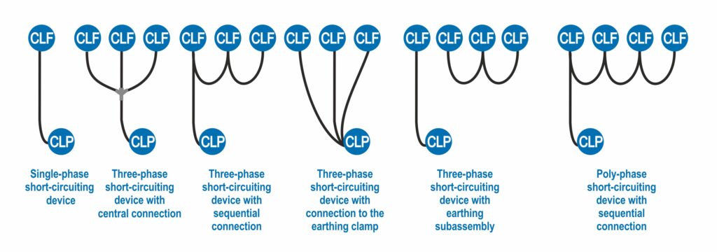
Short-circuiting devices are made in accordance with the provisions of the SR EN 61230 standard, in various constructive configurations: single-phase, three-phase or poly-phase, and can be used both in indoor and outdoor power installations. The short-circuiting and earthing cables can be connected in various configurations, according to the needs.
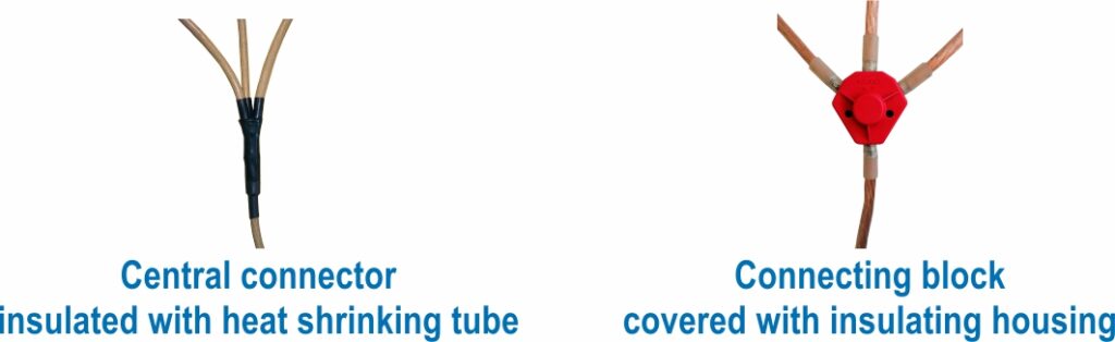
 The central junction of the three-phase short-circuiting devices can be made in two design variants: with a central connector insulated with heat-shrink tube or with a connecting block covered by an insulating housing, which allows inspection of the junction.
The short-circuiting and earthing cables are made of highly flexible multi-core copper wire, class VI, according to the SR EN 60228 standard, and are protected by a transparent insulating plastic layer extruded directly on the multi-core wire, according to the SR EN 61138 standard.
Phase clamps (CLF) and earthing clamps (CLP) are designed and manufactured in a wide range of constructive shapes so that they can be applied on the various shapes of conductors of low, medium and high voltage installations and provide the mechanical strength required to successfully withstand an incident caused by the unexpected occurrence of voltage in the installation.
Even if it may seem less important, the correct selection of phase and earthing clamps allows the user to apply the short-circuiting device in improved ergonomic conditions and, at the same time, with complete electrical safety.
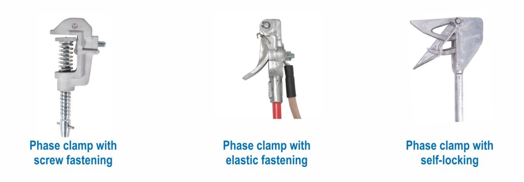
Phase and earthing clamps are fastened on the installation’s conductor or on the earthing bar by various methods:
- Screw fastening (the conductor is firmly clamped between the clamp body and the mobile jaw driven by a screw, sometimes after a pre-fastening of the clamp on the conductor). In this case, the fastening force of the clamp on the conductor is ensured by the manual tightening torque of the driving screw,
- Elastic fastening (the conductor is clamped between the clamp body and the mobile jaw driven by a spring or elastic systems). In this case, the fastening force of the clamp on the conductor depends directly on the characteristics of the spring and on the dimensions of the conductor.
- Fastening by shape and weight (self-locking). In this case, the fastening force of the clamp on the conductor depends directly on the weight of the phase clamp – earthing conductor assembly.
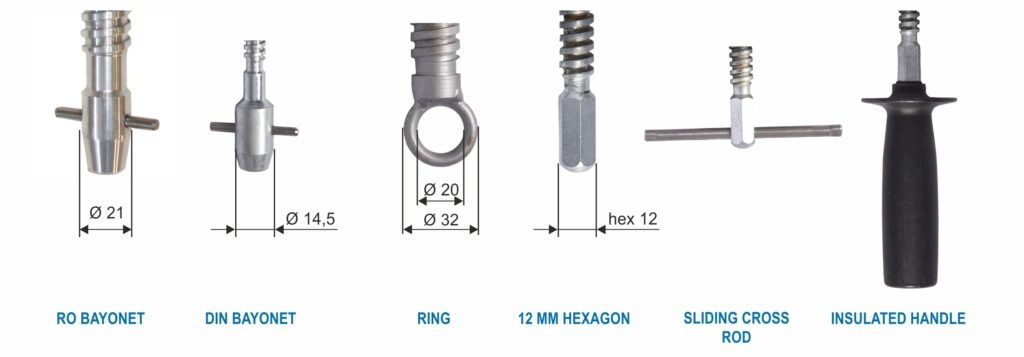
For phase clamps and earthing clamps with a driving screw, the screw can be provided with various terminal ends, allowing the clamp to be coupled to other devices or operated manually.
Screw fastening phase clamps are mainly provided with “RO bayonet” ends, which can be easily coupled to and uncoupled from the “RO bayonet” coupling systems of insulating sticks.
Earthing clamps – since they are applied manually on the earthing bar or other similar elements – are mainly provided with screws with a sliding “cross rod”.
Optionally, phase clamps can also be supplied with other screw terminal ends, such as: “eye” (to be operated with a hook-type part), “DIN bayonet” (a system similar to the “RO bayonet” but with different dimensions), “hexagon 12 mm” (to be operated with a stick provided with a hexagonal coupling system), “insulated handle” (for manual operation).
 Screw fastening phase clamps are made in two constructive categories: “classic” and “automatic”.
The screw clamps in the “classic” category are provided with a simple driving screw that moves the jaw and tightens the clamp on the conductor.
The screw clamps in the “automatic” category have a system of levers and springs that moves the jaw automatically when the clamp touches the conductor on which it is to be fastened, a movement that pre-fastens the clamp on the conductor. After this stage, the clamp must be firmly tightened on the conductor by operating the screw and locking the position of the jaw.
Elastic fastening or self-locking clamps can also be included in the “automatic” category, since once the clamp has been hooked / pushed onto the conductor, the conductor remains fastened between the jaw and the body of the clamp.
Depending on the type of installation and the shape of its conductors / bars, phase clamps are designed in shape and size to allow their simple and safe application on:
- bare conductors of low / medium / high voltage overhead lines,
- bars or parts with rectangular section (clamps for flat bars),
- bars or parts with round section (clamps for round bars),
- spherical parts (ball studs) of various sizes; bars of various shapes (universal clamps),
- terminal parts of installations with various shapes / purposes (encapsulated terminals, sockets for piercing clamps, sockets for HRC fuses, separable connectors, various types of voltage connectors, etc.).
Earthing clamps make the direct connection of the short-circuiting devices to the natural / artificial earth grounding of the power installation or to the mobile earthing rod (the stake of the short-circuiting device).
Earthing clamps are made in several shapes and sizes, depending on the rated short-circuit current to be ensured by the short-circuiting device and on the shape and dimensions of the earthing element.
Earthing clamps are generally “manual” clamps (installed directly by hand on the earthing element).
They can be of “classic” vice-type construction or they can be provided with a “scraping jaw”. When applied and tightened, manual earthing clamps with scraping jaw remove the layers of oxides, impurities and protective paint down to the metal surface, ensuring an appropriate contact resistance. The earthing clamps category also includes special clamps applicable on railway tracks.
Short-circuiting devices can be packed in:
- waterproof fabric bags of various sizes
- plastic cases
- painted metal boxes
The operating temperature range of the mobile earthing and short-circuiting devices is -25 ºC…+55 ºC, and the relative humidity can be up to 100%.
The single-phased mobile earthing devices for stranded flexible conductors, round bars, “T” and “Tr” special pieces or fix couples derivation type from the substations are made in several types in order to provide an ergonomic application of the phase clamps on these round type conductors.

SKU: Msp - CAU - Sp/lp - S/O/P/p

SKU: Msp - CA - Sp/lp - O/p

SKU: Msp - CAEr - Sp/lp - O

SKU: Msp - CAU - Sp/lp - S/O/P/p

SKU: Msp - CAU - 3xSf/If - Sp/Ip - S/P/p

SKU: Msp - C - Sp/lp - P/p

SKU: Msp - C - 3xSf/If - Sp/Ip - P/p

SKU: Msp - CA - 3xSf/If - Sp/Ip - P/p

SKU: Msp - CAE - 3xSf/If - Sp/Ip - P/p

SKU: Msp - CAR - 3xSf/lf - Sp/lp - S

SKU: Msp - CCU - Sp/lp - O

SKU: Msp - CCU - Sp/lp - S/O/P/p, Msp - CA - Sp/lp - O/P, Msp - CCTU/E - Sp/lp - O/p

SKU: Msp - C - 3xSf/lf - Sp/lp - P/p , Msp - CA - 3xSf/lf - Sp/lp - P/p

SKU: Msp - C - Sp/lp - P/p , Msp - CA - Sp/lp - P/p

SKU: Msp - CCRU/E - 3xSf/lf - Sp/lp - S/O/P/p , Msp - CCNU/E - 3xSf/lf - Sp/lp - S/O/P/p, Msp - CCTU/E - 3xSf/lf - Sp/lp - S/O/P/p

SKU: Msp - CCRU/E - Sp/lp - S/O/P/p, Msp - CCNU/E - Sp/lp - S/O/P/p, Msp - CCTU/E - Sp/lp - S/O/P/p

SKU: Msp - 3x35/If - 35/Ip - F/p

SKU: Msp - KA - 3x50/If - 50/Ip - K/p

SKU: Msp - CCU - 3xSf/lf - Sp/lp - S/P/p , Msp - CAU - 3xSf/lf - Sp/lp - S/P/p , Msp - CARU - 3xSf/lf - Sp/lp - S/P/p

SKU: Msp - CCU - Sp/lp - S/O/P/p, Msp - CAU - Sp/lp - S/O/P/p, Msp - CARU - Sp/lp - S/O/P/p